- Windchill PDM Essentials
- Windchill PDMLink
- Windchill ProjectLink
- Windchill PartsLink
Imagine if you could manage quality, reliability, and risk at every stage of your product’s life cycle. You could reduce costs, speed innovation, and enhance next generation products. PTC’s product lifecycle management (PLM) software, Windchill, lets you do just that.
Want to see an example of how Windchill software is used? See how Virnig Manufacturing uses PTC Windchill to change the way their data is delivered within their organization.
Already using Windchill and need help with admin and support? You’ll want to check out our Alliance Program, provided to our customers for on-going technical support, business process consulting, and mentoring services on a monthly basis.
Already using Windchill but you or some of your team member don’t use it often, therefore, it gets confusing? You’ll want to check out our role-based apps for casual Windchill users – EAC Productivity Apps or ThingWorx Navigate will help you.
Don’t know what the heck PTC Windchill is? Then read on.
What is PTC Windchill?
PTC Windchill is a product lifecycle management (PLM) application suite that leverages a consolidated view of product information through multi-system data. It’s a systemic enterprise wide approach to maintaining product and process quality throughout the entire product lifecycle.
PTC Windchill PLM software provides a complete functionality dimension to help organizations capture product structures from computer-aided design tools, transform them into full engineering bill of materials (eBoMS), to manufacturing bill of materials (mBoMS), to service bill of materials (sBoMS) all while retaining the linkages between different perspectives on the product. Windchill solutions break down organizational barriers, allowing teams to work faster and more accurately all while reducing time-to-market and cutting costs.
The Windchill Product Lifecycle Management system can help streamline your product development and service information processes. It’s a system that can help your organization create better products, with more variations, faster, at a lower cost. As a manufacturer, your pressures are not only continual – they’re mounting. Your industry is changing. Your customers’ requirements are evolving. And your supply chain is constantly adjusting to
Windchill helps with exactly that. As an integral component of PTC ’s Product Development System, Windchill manages all product content and business processes throughout the product and service lifecycle. And it has a robust, high-performing architecture to help you today – and to prepare you for tomorrow’s uncertainties. Windchill provides a rich systematic approach for creating, configuring, managing and reusing product structures and associated content, such as CAD files, documentation, requirements, manufacturing information, service information, part/supplier data, calculations and illustrations.
Windchill can also play an important role in increasing your company’s competitiveness by allowing continuous improvements and automation of business processes and procedures. Windchill is an
PTC Windchill Cost
PTC Windchill made updates to their PLM packaging and pricing – which means you can customize dashboards and product data more than ever before at a cost that makes sense for your organization. Here is a breakdown of the new PLM structure.
PTC Windchill Certification
Once you’re ready to purchase the software, you’ll need to make sure it’s learned and understood in a timely manner and without frustration. We have a few options:
Short-Term Support: EAC’s Product Development System Services Team has a long track record of successfully implementing Windchill products.
Long-Term Support: Check out our Alliance Program – EAC’s PTC Windchill system administration and support services for on-going technical support.
Support at your own pace: Your team can get PTC Windchill certified by taking our classes we offer for end users and managers. Check out our training schedule.
The Windchill Products Explained:
Windchill products are application modules that offer users specific sets of features and capabilities within the Windchill application suite. Some of the most common Windchill PLM modules include:
What is Windchill PDM Essentials?
PTC Windchill Product Data Management (PDM) Essentials is built on PTC’s production proven PTC Windchill software.
Windchill PDM Essentials simplifies data management activities by transparently incorporating them into the design process. It manages all forms of information such as CAD drawings, customer requirements, schematics and Bill of Materials (BoMs) that are generated during product development.
This modern product data management solution makes it easy to manage, share, and review your data. It’s finally possible to have a single view of the latest product data, along with tighter integration to major end CAD vendors, Microsoft Office, and desktop tools. Plus, it allows your users to save time with better version control, automated data release, and simple search capabilities. Learn more by reading the PTC Windchill PDM Essentials Data Sheet.
What is Windchill PDMLink?
With an abundance of data dispersed throughout your organization, how do you maintain the integrity of your product information when multiple people are working on the same files? The solution is easy – Windchill PDMLink.
Windchill PDMLink is a Web-based, industry-proven Product Data Management (PDM) system that supports geographically dispersed teams while managing critical processes such as content, change and configuration management. Windchill PDMLink maintains the integrity of your product information by storing master data in a secure area where you can control, monitor, and record all changes.
When a change is made to your data, Windchill PDMLink stores a modified copy of the data, signed and dated, in a secure area alongside the old data, which remains in its original form as a permanent record. In addition to providing change control management, Windchill PDMLink enables you to manage your product’s release cycle as well as its configuration. Check out the PTC Windchill PDMLink Data Sheet for more information.
What is Windchill ProjectLink?
Windchill ProjectLink is a collaborative product development web-based environment that automates and tracks projects.
ProjectLink provides a common workspace where you and your team can share and discuss documents and product structures, hold meetings, and communicate and track progress on tasks. From private exchange environments to public business to business (B2B) exchanges, ProjectLink is a secure web-based system that can easily be used in any collaboration environment.
It can also be used well beyond the engineering and manufacturing departments of your organization. Any project that requires team members to share electronic information such as writing annual reports to
What is Windchill Partslink?
Windchill PartsLink is a module for PDMLink that adds part classification-based features.
PartsLink enables you to perform parametric attribute searching and manage your results through convenient navigation and searching. You can search parts by typing a free-form product description or a part number in the search criteria text box. You can browse the hierarchically organized structure of your parts using text and images. You can also refine your search by constraining parameters in a parametric search.
Windchill PartsLink enables your team to perform similar part searches, expanding your search to look for matching parts that have parametric attributes that are within a certain percentage or absolute tolerance of the selected part. Additionally, you can export the result set to a file.
Many companies lack a comprehensive part search system and as a result they lose the benefits of reusing product components. Criteria-based searching limits the result set, which helps a great deal in reuse decisions. PTC Windchill PartsLink helps solve that problem.
What is Windchill Quality Solutions?
Depending on your specific Windchill Quality Solutions suite (Windchill Quality Solutions 10.1 Desktop, Windchill Quality Solutions 10.1 Administrator, Windchill Quality Solutions 10.1 Web Access) you may have access to one or more applications.
Windchill Quality Solutions, the desktop version, is the cornerstone of the Windchill Quality Solutions suite. It is available in both the team and enterprise additions and is the feature rich windows application for all of your reliability and maintainability activities.
Available in the enterprise addition you will also find Windchill Quality Solutions Administrator which provides you options for administrative controls including options to support secure login.
Windchill Quality Solutions Web Access available specifically for Windchill FMEA infractions in the enterprise edition, allows you access for data entry, filtering, graphing, reporting and more.
Is there other Windchill Software for product data management and process management?
- Windchill MPMLink acts as an integral solution for Manufacturing Process Management.
- Windchill FlexPLM is a product lifecycle management solution that is widely used for retail, footwear & apparel and consumer product companies.
- Windchill Requirements Management is a combination of PTC’s Integrity product and Windchill PDMLink that manages product data software and hardware requirements.
- Windchill PPMLink is a program that provides portfolio management capabilities to discrete manufacturers.
- Windchill Service Information Manager creates associative, interactive service parts information used throughout a product’s serviceable lifecycle.
- Windchill Service Parts improves service operations by enabling service information to be organized and optimized for accuracy, applicability, and rich, graphics-driven delivery.
Want to see a PTC Windchill tutorial to see the software in action? Watch this on-demand video of Windchill’s basic software capabilities.
Manufacturers always try to find a ways to streamline processes and ‘do more with less.’ It drives success in a world full of competition. One way organizations do this is by reducing process complexity with powerful product life cycle management (PLM) or change management software. Connecting your team directly to live operational data increases efficiency in all departments and allows your organization to save money and manufacture products faster.
EAC Product Development Solutions has partnered with PTC, the world’s product development technology leader, to bring organizations the products and services that they need to succeed in their industry. As a PTC Solutions Provider, we provide the maintenance, support, configuration, and training you need to implement change management software as easily as possible.
PTC Windchill Data Management
If you’re looking to do things like keeping better track of files, create and store Bill of Materials (BoMs), put CAD models and drawings in one place, eliminate the risk of two individuals working on a file at the same time, or secure your data without burdening IT – you’re looking for PTC Windchill.
PTC software – specifically Windchill – is a complete PLM solution that provides capabilities such as:
- Bill of Materials (BoM) Management (EBoM, SBoM, MBoM)
- Configuration and Change Management
- Requirements Capture Management
- Early insight into product quality, reliability, and risk
- Efficiently making product variations with a structured platform
- Product Data Management
- Collaboration across all departments with accurate, up-to-date information
- Seamless software integration and defining standards
PTC Windchill is a PLM solution that provides a smooth transition from design to manufacturing with universal access to all critical product data information so that the process isn’t fatigued with delays.
PTC Windchill, Change Management, eBoM Case Study
ALM Positioners, a leading manufacturer of positioner lifts located in Rock Island Illinois, needed PTC Windchill. The company offers unique, customizable weldments and assemblies that require a lot of CAD models and other product information from engineering before manufacturing even begins. Due to extensive product customization and configuration depending on the needs of their customers, ALM needed a better solution to manage product data. They were drowning in paper files – a lot of which had outdated information.
EAC’s implementation team helped ALM Positioners transition to a digital workflow using PTC’s Windchill software. Windchill helped ALM save up to 4 hours per project by integrating EBoMs and MBoMs into their ERP system.
Watch the ALM Case Study on PTC Windchill to see how it has consistently proven to be a leader in the industry and outperformed competitors when it came to product lifecycle management.
Part II – (You can read part 1 here) Evolving your BoM strategy, tools, and abilities. “EBoM vs. MBoM” transforms into “EBoM integrates with MBoM.” This integration includes associativity to one another, time saving tools, elimination of error prone manual steps & more.
Imagine eliminating the common disjointed processes, additional time, and error prone manual steps involved in the creation of downstream BoMs from Engineering into Manufacturing, Production and Service management.
Concepts & examples such as Manufacturing Bill of Materials (MBoM) are shown below, all under one system, integrated & associated, and created with a single click. Then they’re easily edited to meet downstream BoM needs.
BoM creation can be streamlined & improved by associatively creating downstream BoMs (S or M or other) and eventually, connecting them to your ERP system. For now, we’ll focus on the first step of this business transformation concept; the creation of the second, or downstream M or SBoM, starting with a simple EBoM example, created in minutes, and easily viewed & tracked.
Who should be involved in this topic at your company? Ideally, your Configuration Manager role should be leading or heavily involved in this process.
The starting point & tool is PTCs Windchill and your willingness to change & improve.
Once your CAD data is ready to check into Windchill, there is an option (check box) to auto-associate the EBoM to a downstream BoM such as an MBoM. It is a 1:1 relationship for starters. Options can branch out from here into many CM (Configuration Management) directions. Such as multi-level BoM management, uses, visualization and more.
Once created, you can manipulate & edit the default 1:1 downstream BoM to your needs; adding bulk items, manufacturing specific sub assemblies, (build throughs) even new service end items. You can also flatten out an EBoM to meet assembly or production needs. BoM items such as adhesive, lubricant, paint or coatings, packaging items, all things that typically are not on an EBoM, can and do belong on the M or SBoM.
If this fits your company’s needs? consider using Windchill’s auto-associate feature.
This article covers a couple examples. If this is not deep enough…here are even more tools to consider. Topics such as creating associated manufacturing instructions, work instructions, work plans and more. Change Management is shown as reference only, it is an optional element of Windchill for another blog.
There are many options to this topic, these are common examples that fit a lot of needs and is considered a starting point.
1stexample shows all BoM & change components all connected in one system vs. manually done in silo fashion, which is industry’s most common method today. These examples are shown in PTCs Windchill reference viewer tool, which ties all related objects into view for easy visibility with just a few clicks.
- 1. EBoM structure (highlighted in green)
- 2. Change requests, notices and tasks (highlighted in red)
- 3. MBoM structure (highlighted in blue) with their own, or connected Change Management Requests, Notices & Tasks
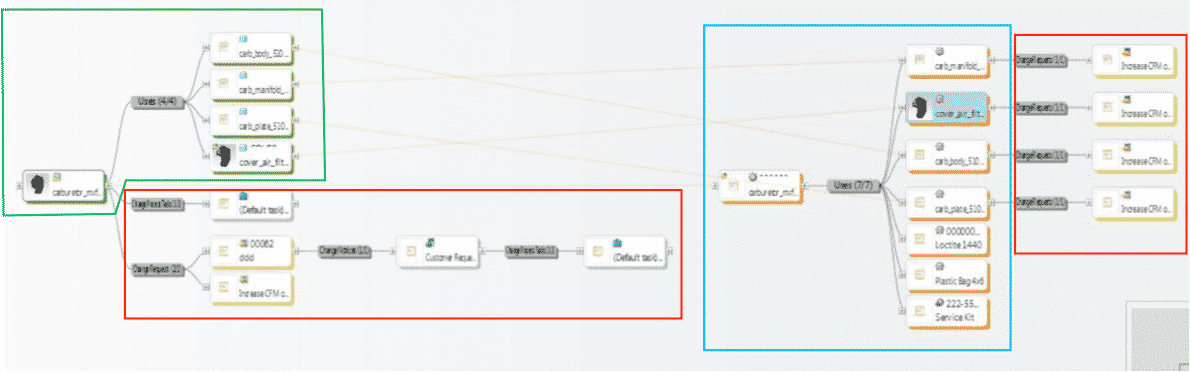
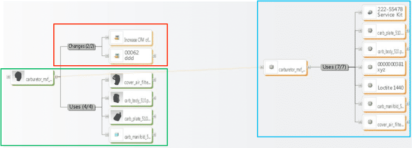
2ndexample shows an EBoM, SBoM (Service Kit in this example), with a saleable end item service kit, as well as components for service or manufacturing BoMs. It also shows Changes, these can also be created, edited, routed, approved or rejected, and even include the SBoM if need be.
Please connect with EAC to learn more, to discover your company’s transformation opportunities with an assessment, maybe see a demo, or attend a webinar. The goal is to help your company transform how you design, manufacture, connect to and service your products.
In last week’s post I walked through a manufacturing use case without Product Lifecycle Management (PLM). I hope you noticed the possible issues and costs related to restricting Manufacturing direct access to PLM and engineering data.
If you missed last weeks post, you can read it here:
Product Lifecycle Management in Manufacturing: Part 1
This week I will use the same use case story. The only difference will be manufacturing has access to PLM. I have also included manufacturing specific modules, which are run through PLM as well. Manufacturing has access to these modules and uses them for all Manufacturing planning.
As before, Engineering completes a new product design and starts a release process of the product in PLM. One major difference now, is Manufacturing personnel are included at appropriate points in the new release process. There is a full integration between PLM and Enterprise Resource Planning (ERP) systems as well. This integration allows for automatic transfer of the Manufacturing Bill of Materials (BoM) to Enterprise Resource Planning (ERP) when appropriate based on processes managed in PLM.
One thing to note on the outline below; each system task, since it is in PLM, has links to all the required information engineering released as well as any supporting information. This is including manufacturing information, customer specification, and supplier specifications on purchased parts.
Part 1: Release Process
The lead Manufacturing Engineer receives a PLM task asking him to begin manufacturing planning for this associated new products design.
Part 2: Manufacturing Planning
The manufacturing engineer begins the layout of manufacturing processes in the PLM Manufacturing Planning System. This includes planning at each work cell. Each cell is linked to required resources, parts, CAD data, and manufacturing documents required to complete that cell action. With the correct system, this will have included all metrics required to properly and completely plan a manufacturing process.
If required, a Manufacturing BoM is based off of, and linked to, the Design BoM. This allows the Manufacturing Engineer to restructure the BoM as needed to allow for the most efficient manufacturing processes without losing ties to the design BoM and parts the manufacturing BoM was created from.
Once complete, work instructions can be created in web form or be printed to paper from this plan. The work instructions would include links to the correct Engineering data and required manufacturing documentation.
Part 3: Release Process Continues
Once the Manufacturing Engineer completes their planning tasks, all required parts and Manufacturing BoMs, are automatically added and/or updated into the ERP system via an integration to PLM.
During this same process, PLM system tasks are sent to purchasing to start the procurement process.
Tasks are also sent to the tooling designers to start tooling generation.
As mentioned, these tasks are automatically linked to all the required engineering and manufacturing information to appropriately complete each task.
Part 4: Tooling and Controls Tasks
Tooling designers access PLM to generate their tooling data and controlling programs directly from engineering 3D data.
The resulting CAD and other tooling data are also saved to the PLM system. This data is linked to Engineering data, Manufacturing data, and the Manufacturing process plan.
Machining paths and other controlling programs generated are also created and saved to PLM with the same functionality mentioned above.
Having these links from manufacturing to engineering data allows for full impact analyses of any potential changes being planned for the product by the company. As well as insures all downstream data is updated appropriately when an engineering change does occur.
Part 5: In-Process Change by Engineering
While ramp up is happening, Engineering makes a last-minute change. Once the change is complete in Engineering, they start a change process that includes all downstream departments. Each department receives a PLM system task with the all required information related to the change linked to the task. This includes purchasing, manufacturing, tooling, etc. Each department acts upon the change, completing all internal department actions required.
Once all of the departments have completed their tasks in PLM, the change has been completed. Manufacturing ramp up continues leading into the initial manufacturing process.
Part 6: Issue Tracking and Correction During Manufacturing
During the initial manufacturing process, a manufacturing team member notices there is a clearance issue with the design. The team member verbally notifies their cell leader of this issue. The cell leader creates a change request in the PLM System. During that process, he creates a digital markup that is saved with the change request. The change request is created referencing the engineering data the issue is related to.
The engineer responsible receives a PLM system task notifying of this problem. The engineer takes the needed corrective actions and updates the CAD data. This CAD data is then revised released and included in the problem report.
The cell leader receives the notification the problem report was approved and corrected. The updated CAD data is included, the cell leader and the manufacturing floor team member can now reference the new data directly from PLM and make the needed correction.
This happens many times during the initial manufacturing process. The necessary PLM processes are initiated based on the issues found during the initial manufacturing run.
Manufacturing uses PLM to gain access to engineering data because it always references the latest released information. This insures nothing is made from outdated information.
Part 7: Final Product Release
The final product is released to the customer.
All as-built information has been saved in PLM, meaning most of the related engineering data has been changed via the PLM process capturing changes. Anything that hasn’t been corrected yet is also saved via electronic markups to be processed later.
Part 8: Another Manufacturing Run
One year later, the company needs to do a manufacturing run on this same product. However, they have a large turnover with their manufacturing employees. Only a few people are there that worked on the first production run of this product. Without the use of PLM, this could be a disaster. However, all as-built changes where captured in PLM for the first production run of this product and manufacturing is still using PLM to access all build information. This allows manufacturing the ability to properly prepare for the next run. This resulted in very few, if any, issues during the next production run.
Hopefully it is easy to see the benefits of giving manufacturing direct access to PLM, even based on this limited use case example.
There are many benefits to utilizing PLM in manufacturing. Much more than is appropriate to list in a blog. If you’d like to take a deeper dive, please contact one of our experts here at EAC. We would love to talk you through all the benefits PLM utilized in manufacturing could offer you.
In the meantime, reading our eBook, “Designing an Effective Change Control Process” may be helpful. We walk you through how to design a change control process to improve productivity and reduce quality issues.

Many still think that a Product Lifecycle Management (PLM) system is only for the Engineering department. At one point that may have been true. However, I am starting to see a shift in that mind set. More companies every day are starting to see the benefit, and even the necessity, in giving manufacturing direct access to the appropriate engineering data through a robust PLM system.
In this two part series I am going to outline a fictional use case both with and without PLM. My intent is for this to highlight the benefit of PLM in manufacturing. Please realize the use cases are not all inclusive. There are many possible actions that need to be taken to start manufacturing of a new product. I am simplifying for purpose of maintaining a storyline that is easier to follow along.
In the first use case, engineering is working in a PLM system and Manufacturing is not. Engineering uses PLM for data management, process management, and controls their release process utilizing this system. However, only engineering has access to this PLM system.
When a new product is released to manufacturing, only the drawings associated to this product are printed on paper and put in a folder and then physically handed to manufacturing. Once manufacturing has this folder, they begin the required tasks to begin production of this product. I will outline below what a possible workflow might look like in manufacturing without a PLM system.
Part 1: Initial Manufacturing Product Release Tasks
The required parts are manually entered into the Enterprise Resource Planning (ERP) system. In many cases, the parts are entered into a manufacturing Excel file instead. Requests made to purchasing to procure parts and raw materials required, utilizing copies of the 2D prints to send to the suppliers. After that, a Bill of Materials (BoM) structure for the parts is manually created to support the required manufacturing processes.
Part 2: Process Planning
Manufacturing will then begin the layout of processes required to manufacture the product. In many cases, the layouts are also created in Excel.
Part 3: Tooling and Controls Design
The tooling designers recreate the required 3D models from the 2D prints. The designs are typically saved in an uncontrolled manner such as on a local drive on a user desktop. The machining paths and other controlling programs are generated from these uncontrolled tooling files as well.
Part 4: In Process Engineering Change
While the ramp up is happening, engineering has the ability to make last-minute changes. If a change is made, a new 2D print must be created and supplied to manufacturing. Manufacturing must attempt to replace all copies of the printed design with a new copy. When this happens, there is great risk associated with having two of these copies floating around. Designers are manually notified to make the required changes, as are the supplies to make the required changes to the new prints. Manufacturing planning must adjust processes based on these changes as well.
Part 5: Finish Ramp Up
Manufacturing ramp up continues leading into the initial manufacturing process.
Part 6: Begin Initial Manufacturing Run
During the initial manufacturing process, a manufacturing team member notices there is a clearance issue with the design. The manufacturing team member verbally notifies their cell leader of this issue. The cell leader will then make a phone call to the engineer whose name is on the print and explains the problem. The engineer tells him to grind down the part to allow the needed clearance. The cell lead marks by hand on the print how much the part must be grinded down. If the engineer remembers, he will also update the 3D design to match this. It’s unlikely they would request a formal change to be release. One thing to note here is that there is no history of this interaction anywhere but on the market up print on the manufacturing floor.
This happens many times during the initial manufacturing process. Typically, only major issues are formally documented which will drive a full change process in Engineering.
Part 7: Out-of-date Information on Manufacturing Floor
One sub-assembly was made using out-of-date information due to outdated prints being used. Rebuild of this sub-assembly was required.
Part 8: Product Release
The final product is released to the customer.
Most of the as-built documentation is saved on paper in a folder in the manufacturing offices.
One year later, they need to do a manufacturing run on this same product. However, they have a large turnover with their manufacturing employees. Only a few people are there that worked on the first production run of this product. They were not aware of the as-built mark-ups manufacturing had in their folders. So, many of the same issues were found and had to be corrected in this manufacturing run again.
I listed a few possible issues that could come from uncontrolled information used in manufacturing. I am sure you can imagine, or even experienced other possible issues.
Keep your eyes peeled for next weeks post where I review the same manufacturing process, but this time with manufacturing having direct access to Product Lifecycle Management (PLM). If you would like to learn more about the benefits of PLM in manufacturing you can download our eBook, “Designing an Effective Change Control Process” here. This eBook discusses how following a change control process would likely improve productivity and reduce quality issues. The benefits of having a controlled process in place substantially outweigh the initial time and resources to get started.